Thermocouple Diagnostics: The Physics of the 30mV Safety Loop, Cool-Down Failures & the 3-Step Field Test

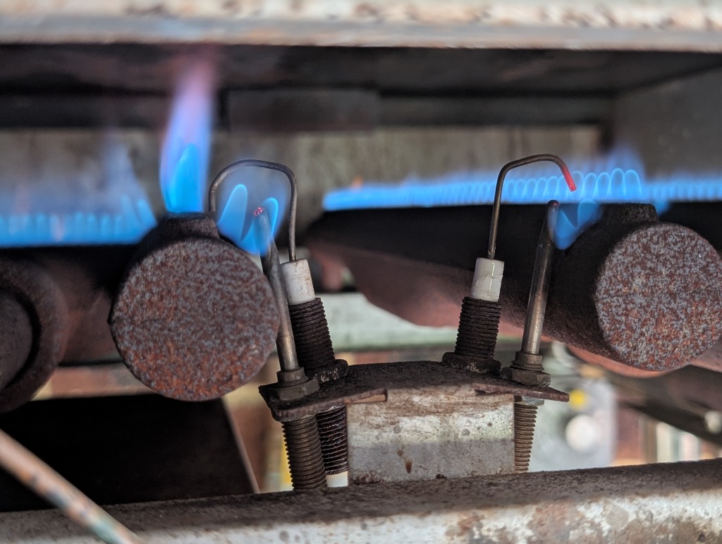
Every gasfitter in the trade has lived this exact scenario: You get a service call for a standing pilot that won’t stay lit. You hold the knob down for a full minute, release it, and click, the pilot snuffs out immediately.
The most common reaction? Grab a generic replacement thermocouple from the back of the van, screw it in, and hope for the best. But when you light the pilot again and the valve still drops out, you're left scratching your head, wasting billable hours, and wondering whether to condemn an expensive gas valve or second-guess your brand-new thermocouple.
To stop guessing and start diagnosing, you must understand the underlying physics driving the 30-millivolt thermoelectric safety loop. With a standard digital multimeter and an inexpensive test adapter, you can isolate whether the problem is a degraded thermocouple, a high-resistance wiring loop, a burnt-out electromagnet (E-Mag coil), or a dangerous sticking valve seat in under three minutes.
1. The Physics of the 30-Millivolt Safety Loop
Unlike modern flame rectification rods that rely on 240V or 24V electronic control boards, standard standing pilot thermocouples operate entirely independent of external power grids. They are microscopic thermal power plants, utilizing thermal energy to generate direct current (DC) electricity via the Seebeck effect.
A standard thermocouple is constructed from two dissimilar metals: a rigid outer copper sheath and an internal Constantan (a copper-nickel alloy) wire, separated by high-temperature electrical insulation. These two conductors are fusion-welded together at the tip to create the "hot junction."
When the 600°C to 800°C pilot flame impinges on the welded tip, a steep temperature differential (ΔT) is established against the "cold junction" at the threaded base inside the cooler appliance vestibule. This thermal gradient causes excited electrons to migrate from the hot end to the cold end at different rates across the two metals. The result is a continuous DC output of approximately 25 to 35 millivolts (mV).
This tiny 30mV signal travels down the coaxial lead directly to the gas safety valve. Inside the valve housing sits an electromagnet (E-Mag coil). When you manually depress the pilot knob, you are physically pushing the valve plunger against a heavy internal safety spring and seating the armature against this electromagnet. The 30mV current energizes the coil with just enough magnetic flux to hold that spring-loaded plunger open on its own.
If the pilot flame blows out:
- The hot junction cools down in seconds.
- The temperature differential (ΔT) collapses.
- Millivolt output plunges below the magnetic holding threshold (typically below 5 mV).
- The internal spring violently snaps the rubber seal shut, instantly isolating the gas supply.
This failsafe sequence is mandated by Australian and international standards, including AS/NZS 5601.1 and AS 3814:2018 (Clause 2.25.5). Under Clause 2.25.5, a maximum flame failure shut-off time of 45 seconds is permitted only for manually-ignited atmospheric burners (or those with manually-ignited permanent pilots) where the total combustion chamber input does not exceed 500 MJ/h. Larger appliances or forced-draught systems mandate significantly faster response times (15s or 3s).
2. Know Your Tech: Thermocouple vs. Thermopile vs. Flame Rod
Before pulling out your multimeter, you must confirm exactly what flame safety technology is installed. Mixing up diagnostic parameters leads to misdiagnosis:
| Feature | Standard Thermocouple | Thermopile (Powerpile) | Flame Rectification Rod |
|---|---|---|---|
| Operating Principle | Thermoelectric generation (single hot junction) | Multiple thermocouples wired in series internally | Flame ionization (conducts and rectifies AC to DC) |
| Power Source | Self-generating via pilot flame heat | Self-generating via pilot flame heat | External AC supply from ignition control module |
| Signal Output | 25 to 35 mV DC | 500 to 750 mV DC | 2 to 10 μA DC (micro-amps) |
| Primary Role | Holds open the manual gas valve pilot E-Mag safety seal | Powers the main gas valve coil AND millivolt room thermostat | Signals electronic ignition module to keep main solenoid open |
3. The Notorious "Cool-Down" Failure Phenomenon
One of the most baffling complaints gasfitters receive from homeowners and facility managers goes like this:
"The hot water system was working perfectly! We only turned the pilot off for two weeks while on holiday. Now we can't get the pilot to stay lit. How could it break while it was turned off?"
This is not user error, and it’s not bad luck. It is a predictable metallurgical fatigue failure driven by differential thermal expansion:
- Relentless Thermal Cycling: When an appliance runs, the thermocouple tip operates between 600°C and 800°C. Copper and Constantan expand and contract at completely different rates (copper expands significantly more under heat than Constantan).
- Microfracture Formation: Over years of service, thousands of heating and cooling cycles create mechanical stress at the internal weld or along the heat-aged Constantan core wire. Eventually, microscopic fractures form across the conductor.
- The Hot Bridge Mask: While the appliance is firing, extreme heat expands both metals outward. This thermal expansion physically wedges the broken edges of the microfracture together, bridging the gap and preserving electrical continuity. The appliance keeps firing without a hint of failure!
- The Cool-Down Sever: When the appliance is switched off, the assembly cools to ambient temperature. The metals contract. As they shrink, the fractured edges pull apart, permanently severing the connection.
The circuit is now completely open. The moment someone tries to relight the pilot, the dead thermocouple cannot generate even a fraction of a millivolt, and the gas valve will never hold.
Site Tip: The "Splash Zone" & Overheated Cold Junctions
Never forget that the Seebeck effect requires a temperature differential (ΔT) between the tip and the base. If the base overheats, voltage drops even if the tip is blazing hot.
If a flue draught diverter is spilling hot combustion gases back into the burner vestibule, or if a dirty pilot orifice causes a lazy yellow flame that washes over the entire pilot bracket, the "cold junction" at the base can exceed 250°C. As the base temperature approaches the tip temperature, ΔT collapses, millivoltage plummets below the drop-out threshold, and the pilot shuts down despite a roaring flame. Always check for soot and clean the pilot injector before condemning components.
4. The 3-Step Diagnostic SOP: Stop Guessing, Start Testing
To pinpoint thermocouple and valve faults on site with 100% accuracy, follow this 3-step Standard Operating Procedure (SOP) using a digital multimeter set to DC millivolts:
1 Open Circuit (OC) Test: Unloaded Output
Target: 25–35 mVProcedure: Unscrew the thermocouple lead completely from the gas valve. Clip your negative meter lead to the outer copper sheath and touch the positive lead to the insulated brass contact button at the threaded end. Light the pilot flame manually and heat the tip for 60 seconds.
- > 20 mV (typically 25–35 mV): PASS. The internal Seebeck junction is generating healthy electromotive force.
- 15 to 20 mV: MARGINAL. Inspect flame impingement, check for soot buildup on the tip, or service the pilot injector.
- < 15 mV: FAIL. Replace the thermocouple immediately. The internal junction is degraded or fatigued.
2 Closed Circuit (CC) Test: Loaded Stress Test
Target: 10–15 mVWhy it matters: A thermocouple can easily pass an Open Circuit test (showing 28mV) while floating with zero current draw, but the moment you connect it to the electromagnet, the voltage collapses. Why? Because internal corrosion or hairline microfractures introduce high internal electrical resistance.
Procedure: Screw a threaded brass thermocouple test block adapter into the gas valve port, screw the thermocouple into the adapter, and attach your meter leads to the adapter test terminals while the pilot is burning.
- 10 to 15 mV (approximately 50% of OC): PASS. The circuit is carrying healthy current under load.
- < 8 mV: FAIL (Replace Thermocouple). The voltage collapsed under load due to excessive internal resistance.
- CC ≥ 80% of OC (e.g. OC is 28mV and CC is 25mV): FAIL (Replace Gas Valve E-Mag). If the voltage barely drops under load, the electromagnet coil is open-circuit or drawing no current!
3 Drop-Out (DO) Test: Valve Magnet & Spring Health
Target: 1–5 mVProcedure: With your meter still connected to the test adapter, blow out or turn off the pilot gas supply. Watch the digital display as the voltage decays and listen carefully for the audible "snap" of the valve spring slamming shut. Note the exact millivolt reading at the instant of release.
- 1 to 5 mV (within 45 seconds): PASS. The electromagnet and safety spring release cleanly within the AS 3814:2018 Clause 2.25.5 shut-off timing envelope (permitted for atmospheric systems up to 500 MJ/h).
- > 5 mV (Premature Drop-Out): FAIL (Replace E-Mag / Valve). A weak electromagnet or overly stiff spring causes nuisance pilot outages during slight gas pressure fluctuations.
- < 1 mV or Fails to Release: CRITICAL DANGER: STICKY VALVE! If the valve holds open below 1mV or doesn't snap shut when cold, the internal seat is varnished, corroded, or mechanically stuck. The appliance will continue leaking unburnt gas if the pilot blows out! Condemn and replace the valve immediately.
Stop Guessing Millivolts in the Field
You don’t have to memorize voltage thresholds or second-guess whether a 9.2mV reading under load is a bad coil or a failing sensor. Enter your Open Circuit, Closed Circuit, and Drop-Out readings into GasCalc's Thermocouple Diagnostics Wizard.
5. Phantom Faults: Check These Before Condemning the Sensor
Field data indicates that a staggering percentage of thermocouples are discarded when the actual fault lies elsewhere in the loop. Always rule out these three common phantom faults:
A. Thermocouple Interrupters & High Contact Resistance
Many boilers, water heaters, and pool heaters route the millivolt circuit through an Energy Cut-Off (ECO) spill switch or high-limit thermostat via an interrupter block.
Because the circuit operates on a microscopic 30 millivolts, Ohm’s Law (V = I × R) is ruthless. Even 0.5 ohms of oxidation, dirt, or a loose spade terminal will swallow the millivoltage before it ever reaches the electromagnet coil. Always test the ECO switch with your multimeter set to low ohms (Ω); it must read near absolute zero resistance.
B. Crushed Insulators: The Overtightening Trap
When fitting a new thermocouple into the back of a gas valve, overtightening the brass gland nut is the single most common amateur mistake.
Inside the base of the thermocouple is a microscopic insulating washer separating the positive central conductor from the negative copper sheath. If you crank down on that nut with a 10mm spanner, you crush that insulator, creating a permanent internal dead-short. The brand-new thermocouple will never work.
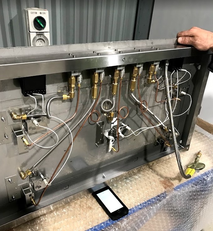
Notice the gentle coiled expansion loops in the copper thermocouple capillary tubes shown in the hotplate underside above. A frequent amateur mistake is pulling capillary leads drum-tight or kinking them sharply at 90-degree angles around sheet metal brackets. A sharp crease pinches the outer copper sheath directly into the inner Constantan core wire, causing an instant internal dead-short. Always form smooth radius loops to provide strain relief and allow for natural thermal expansion as the appliance heats and cools.
C. Oxygen Depletion Sensors (ODS) Doing Their Job
In flueless space heaters, the standing pilot assembly contains an Oxygen Depletion Sensor (ODS). If room oxygen levels drop from the normal 20.9% down toward 18.5%, the pilot flame is aerodynamically engineered to lift off the thermocouple tip. The thermocouple cools down, drops out the valve, and cuts off the gas before dangerous carbon monoxide builds up.
If a heater shuts off after 30 minutes in a closed room, the thermocouple isn't faulty; the room lacks adequate permanent ventilation. Never drill out, enlarge, or modify an ODS pilot injector.
The Golden Rule: Never Bypass a Thermoelectric Safety Loop
Under no circumstances should a thermoelectric safety device or thermocouple interrupter ever be bypassed, jumpered, or wedged open on a customer’s site.
In the event of flame failure, the control system must initiate a lockout of the affected burner (AS 3814:2018 Clause 3.5.4). Furthermore, Clause 3.4.1.1 strictly prohibits the inclusion of any bypass mechanisms or modifications that would render an interlock, limit device, or safety loop ineffective during standard operation.
The thermocouple is the absolute last line of defence verifying an ignition source before unburnt fuel pools in the firebox. Bypassing it blinds the safety shut-off mechanism. If the pilot extinguishes while the gas valve is held open, unburnt gas floods the combustion chamber and appliance casing. Upon introducing any subsequent ignition source (such as a thermostat relay, an automatic spark, or a match), a catastrophic deflagration or explosion is virtually guaranteed.
6. Summary & Service Van Checklist
Before you pack up your multimeter and write out your invoice, run through this mental checklist:
- Clean before testing: Brush off carbon soot and check pilot injector aeration.
- Check Open Circuit (OC): 25 to 35 mV DC after 60 seconds of steady flame.
- Check Closed Circuit (CC): Must hold 10 to 15 mV under load. If it drops below 8 mV, replace the thermocouple.
- Check E-Mag Ratio: If CC is nearly identical to OC (CC ≥ 0.8 × OC), replace the electromagnet coil.
- Perform Drop-Out (DO): Valve must release between 1 and 5 mV within 45 seconds. Any valve holding below 1 mV is a lethal sticky valve.
- Torque with care: Finger-tight plus 1/4 turn only. Protect the insulating washer.
Disclaimer
This article is provided for educational and technical guidance based on Australian and New Zealand Gasfitting standards (AS/NZS 5601.1:2022 and AS 3814:2018). Gasfitting is a specialized and legally restricted trade. All diagnostic measurements, maintenance, and gas valve servicing must be conducted by licensed gas professionals in strict accordance with manufacturer specifications and local regulatory authorities (e.g. Energy Safe Victoria, Fair Trading NSW, Building and Energy WA, QLD Resources Safety & Health).